This is mine!!
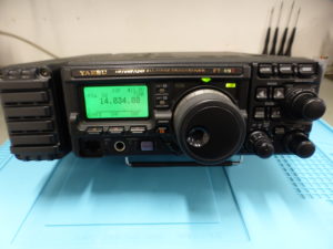
When I bought it ,used, about 2 years ago, was immediately clear to me that the radio had great potential:
portable
100watt
four bands
and with a discreet DSP
But its portability characteristics required to spend more money on battery packs.
I decided to make some changes:
The lower part of the radio can house an FP-30 AC power supply or two battery packs , the idea was to put polymer ion batteries instead of the old NIMH.
These new batteries are widely used in airplane-modeling because they are very powerful, very generous in terms of current delivered and extremely light, associated with a rectangular shape that facilitates positioning.
All fantastic features for my use but the downside is that they need a special charging circuit and are dangerous because if they are short-circuited, they can explode.
This last feature is the one that scares me, but since I am a model maker as well as an amateur radio, I know how difficult it is to make them explode but it is certainly a risk that those who want to do this project must keep in mind. Obviously I do not take any responsibility if following this tutorial someone can damage their radio or get injury.
THIS MOD IS POTENTIALLY DANGEROUS AND I ADVISE ALL WHO ARE NOT EXPERIENCED TO DO IT
If you really can’t do it but absolutely want it in your 897, contact me and I will try to help you.
START
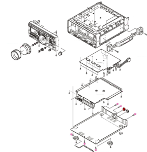
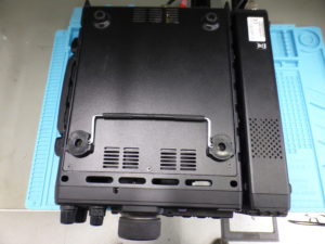
Now take the battery and cut the connections to the socket
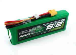
Immediately isolate the red wire with a tape before cutting the black one.
The model I chose is MULTISTAR 3S 5200mAh and I found it here
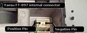
The radio uses two sockets to connect batteries A and B, it is necessary to obtain the equivalent female type connectors
3-pole JST VH headers- 3.96 mm
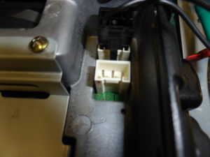
and the pinout:
THE CHARGE SOCKET
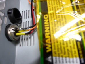
Remove one of the two caps that are used for the standard battery pack and insert the 4-pin din plug
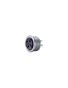
and connect to the radio
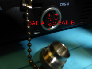
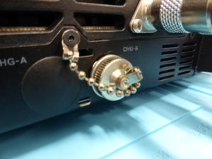
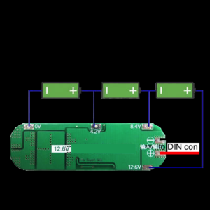
PREPARE THE CHARGING BOARDS
For me the model is:
3S 20A 18650 Li-ion Battery Charger PCB BMS Protection Board Cell 12 PA B0IT
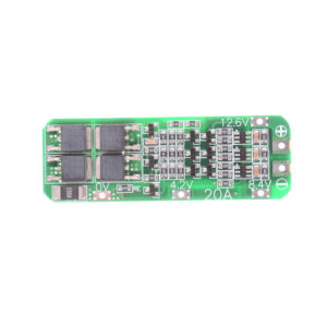
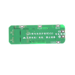
Connections like the picture.
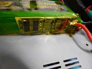
Repeat the operation also for the second battery and connect everything to the sockets.
The batteries are 3s 5200mAh with a voltage of 12-13 volts, the voltage value compared to the originals is slightly lower but with a disproportion in terms of current. This lower value of the battery voltage will cause the comparator that controls the two LEDs on the front of the radio to work incorrectly, but this will not affect the operation of the mod in any way and it will still be a price that you pay for significant increase working time.
The final result:
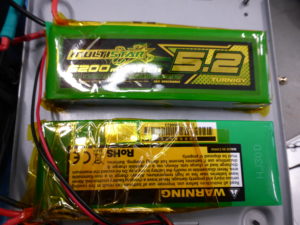
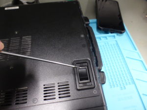
After reassembling and fix everything, with the switch A B placed above the radio you can select which battery pack you want to use in the QSO
HOW TO CHARGE:
To charge our radio we will use a din plug compatible with the socket we put on the RTX and with the contacts:
+ A -A we will connect a 14 volt power supply to charge battery A
+ B -B we will connect a 14volt power supply to charge the B battery.
Nobody forbids us to charge a battery at a time with one single power supply, the charging board will take care of managing the whole cycle without incurring overloads.
Batteries and QSO time?
The time is approximately 6-10 hours depending on the power used and the type of QSO.
These values I have extrapolated from empirical evidence of continued use because it is very difficult to find a rule for consumption on this type of user (too many variables).
IN THE CIRCUIT NO CUT-OFF IS PROVIDED FOR LOW BATTERY.
This type of accumulator is sensitive for overdischarged, one of my suggestions is to avoid dropping the battery below 10 volts, this radio certainly gives us a visual aid.
For any questions or requests please contact me e-mail
